CHICKEN BUS BAR CART

Guatemala inspired • DIY build guide

A little bus.
A big personality.

Meet La Cantinera: a Guatemalan chicken bus turned rolling bar. A welded steel frame, bright paint, chrome flourishes, a roof that lifts to reveal the bar and the hanging glasses — built around a 48-inch footprint.

La Cantinera closed-cart concept
THE CONCEPT • Authentic colors. Hidden bar.
48"OVERALL LENGTH
26"WIDTH OVER FENDERS
44"CLOSED HEIGHT
10BUILD STAGES

01 / The vision

La Cantinera, closed & open.

Closed for the road, open for service. Tap either view to see the full design sheet.

Parked: all chicken bus.Short hood, jewel-blue windows, chrome grille and rails, painted scrollwork and the cart's name lettered down the side.
Serving: the bar appears.Lift the roof, unfold the side shelf, and reveal ice, upright bottles, garnishes and glasses hanging under the open roof.
Concept vs. build. The cart you will build has everything the concept shows — the lifting roof, the hanging glass rail, exposed wheels under fenders — on a welded 1" square-tube steel frame that keeps it strong, light and easy to service. Build from the dimensions in this guide, not from the artwork. The rendering carries an earlier working name; the cart is La Cantinera, with SALUD on the destination board.
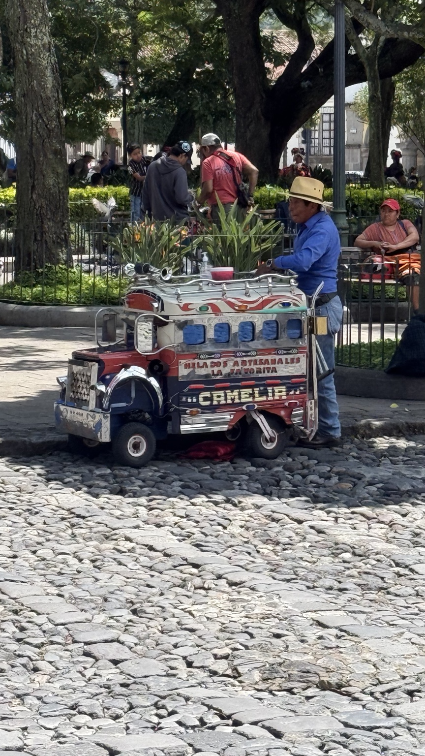
Photograph of a decorated Guatemalan ice cream bus cart on a cobblestone plaza

The real thing

Keep the handmade character.

A real Guatemalan bus cart sets the look: a compact hood, strong red body, shiny silver bands, blue windows, exuberant lettering and roof horns. The build uses that visual language over a steel frame skinned in thin plywood and aluminum.

For the clearest resemblance, spend your detail work on the grille, the front fenders, the roof trim and the side lettering.

02 / Make it fit

Dimensions that work together.

A planning layout in inches. Every height is stacked from the floor, so measure your real wheels and casters first and carry the difference through.

Concept side, front and rear views
Concept proportions: 48" long, 24" wide. This build is 44" tall to the roof and 26" over the front fenders; the table below is the plan.
ComponentPlanning sizeBuild note
Overall closed envelope48" L × 26" W × 44" HBody is 44" × 22"; bumpers add 2" each end; the fenders at both ends set the 26" width; mirrors are removable
Main frame1" × 1" × 0.065" steel tubeBase ring 44" × 20" outside; cabin posts 25"; counter ring 36" × 20"
Front hood / rear cabin8" / 36"Together equal the 44" body; the hood is a void that hides the steering casters
Rear wheels2 × 8" × 2" flat-free, ⅝" axleCarry the rear. Axle 4" above the floor, 4½" forward of the tail, on welded stub-axle tabs
Front wheels (show only)2 × 8" × 2", same as the rearMounted in the front fenders ½" clear of the floor so the cart looks like the concept at both ends
Front casters2 × 5" total-lock swivel, plate mountHidden under the hood; they steer. Their ~6¼" mounting height sets the base ring
Floor½" plywood on the base ringFloor top at 7¾" from the ground
Working countertop34" above floorCounter ring top at 33¼" + ¾" plywood
Clear height inside cabin25½"Room for a 12" drop-in bin, its drain valve and a 3-gallon jug
Counter clear area34" × 18" between postsZones along the length: ice 20" • bottles 7" • garnish 7"
Ice-bin envelope20" × 14" including flangeFlange sets the cutout; keep ≥1" of counter around it
Bottle well7" × 14", platform 5" below counterEight 750 ml bottles stand 8" proud and still clear the closed roof
Lifting upper body36" × 20" × 9¾", ¾" tubeHinged on the long side opposite the shelf; opens to ~70°
Glass railInside the roof, along its free edgeRail is parallel to the hinge so it stays level; ~52" high when open
Open side shelf34" × 10", two folding legsStarts 2" behind the cabin front to clear the fender; 36" total open width
Contents planning limit150 lb, distributedValidate the full assembly in Stage 10; hardware ratings alone are not a cart rating
Side silhouette with heights lifting upper body • window band cabin 36"hood 8" 44" 34" rear: 8" wheels carry the loadfront: show wheels • casters hidden 48" over bumpers • 26" over fenders Top view of the counter zones ICE BIN ENVELOPE20" × 14" BOTTLES7" × 14"5" deep well GARNISH7" × 14"3 × 1/9 pans prep strip, customer side 34" clear 18" hinge side (bartender) at top • shelf side (customers) at bottom
Every height stacks from the front casters. The base ring sits on the caster plates, so if your casters are not 6¼" tall, every number above moves by the difference. Measure them, then set: counter ring top = 34" − ¾" counter; cabin post length = counter ring top − 1" − base ring top. Write your own stack down before you cut steel.
Steel cut list — 1" × 1" × 0.065" square tube (about 44 ft, two 24-ft sticks)
QtyLengthPurpose
244"Base ring long rails
218"Base ring end rails (between the long rails → 20" outside)
318"Base cross members at 8" (hood line), 20" and 32" from the nose
425"Cabin corner posts, welded on top of the base ring at 8" and 44"
236"Counter ring long rails
218"Counter ring end rails
218"Counter cross members at the ice/bottle and bottle/garnish lines
216"Hood front posts
118"Hood top crossbar
28"Hood top rails back to the cabin posts
2 + 420" + 1"Front and rear bumper bars on 1" stand-off stubs
41½" × 3/16" × 4" flat barStub-axle tabs: 2 rear (hole 2¼" from the ring, load-bearing), 2 front (hole 2¾" from the ring, show wheels ½" off the floor)
24" × 4" × 3/16" plateFront caster pads under the hood, drilled to the caster pattern

Upper body — ¾" × ¾" × 0.065" tube (24 ft of pieces; buy two 20-ft sticks). Bottom ring 2 × 36" + 2 × 18½"; roof ring the same; 4 corner posts at 8¼"; 2 roof ribs at 18½". Buy the steel from a local supplier — it is a fraction of the online price and they will cut 24-ft sticks in half for transport.

Plywood cut list — one ¾", one ½", two ¼" sheets

Everything below is skin, floor or counter; the steel carries the load. Allow for saw kerf and label every piece. "Field measure" means cut it to the welded frame, not to this table.

MaterialQtyCut sizePurpose
¾" exterior plywood136" × 20"Counter; cut the bin, bottle-well and pan openings after the hardware arrives
¾" exterior plywood134" × 10"Folding side shelf
¾" exterior plywood18" × 20"Hood top
¾" exterior plywood17" × 14"Bottle-well platform
2 × 2 lumber2Field measure (~32")Shelf legs for the folding leg brackets
½" exterior plywood144" × 20"Floor over the base ring, notched 1" at each post
½" exterior plywood120" × 27"Rear end panel with a lift-off service door
½" exterior plywoodAs neededField measureBottle-well sides, zone dividers, pan-opening lip
¼" exterior plywood236" × 27"Cabin side skins, notched for the front wheel arch
¼" exterior plywood120" × 9½"Cabin front above the hood (the "windshield")
¼" exterior plywood2 + 18" × 17" + 20" × 17"Hood sides and hood front (grille panel)
¼" exterior plywood2 + 236" × 10" + 20" × 10"Upper body sides and ends, window openings cut for acrylic
¼" exterior plywood136" × 20"Roof skin on the ¾" tube roof ring

03 / Shop with a plan

The parts behind the personality.

A welded frame, a thin skin and off-the-shelf bar hardware. Everything here has a specific product on the parts & tools page.

Steel & welding

About 44 ft of 1" × 0.065" square tube and 24 ft of ¾", flat bar for the axle tabs, 3/16" plate for caster pads, .030" flux-core wire, cutoff and flap discs, self-etching primer, corner magnets.

Sheet goods & fasteners

One sheet each of ¾" and ½" and two of ¼" exterior plywood; #8 self-drilling screws for skin-to-tube; exterior wood glue; a 2 × 2 for the shelf legs.

Wheels

Four 8" × 2" flat-free wheels with ⅝" bearings and stub-axle hardware — two carry the rear, two sit in the front fenders for the look; two 5" total-lock swivel plate casters hidden under the hood do the steering.

Roof & shelf hardware

Weld-on hinges for the upper body, a matched pair of gas struts sized after weighing, a positive-locking lid stay, two travel latches, bump stops, weatherstrip, a 36" piano hinge, locking shelf brackets and folding leg brackets.

Bar station

Insulated drop-in ice bin with drain, shutoff valve, food-grade hose, removable waste jug, three 1/9-size pans, a cutting board, a stemware rail and food-safe sealant.

Decorative skin

Thin aluminum sheet for panels and fenders, panel adhesive, blue acrylic for the windows, chrome trim, grille mesh, horns, mirrors, roof rails, vinyl lettering and scrollwork.

Finish

Self-etching primer for the steel, bonding primer for wood and aluminum, gloss enamel in red, royal blue and yellow, chrome spray for the bumpers, edge sealer, exterior sealant, sanding discs.

Optional electrical

Enclosed 12 V battery with its charger, 12 V LED strip, inline fuse, master switch, 18 AWG wire, heat-shrink connectors, grommets and strain relief.

Tools: a 120 V MIG welder with helmet, gloves and jacket; angle grinder with cutoff and flap discs (or a metal-cutting saw); tape, framing square, corner magnets, clamps; circular saw with a rip guide, jigsaw, drill/driver, countersink, random orbital sander; SAE wrenches; a deburring tool; eye, ear and dust protection. Welding needs a ventilated space, a fire extinguisher at hand and nothing flammable within reach of sparks.

Budget: no store prices are quoted here; they change too often. Price the bin, wheels, struts and chrome details before buying. Steel from a local yard is far cheaper than cut lengths online.
Want the exact parts? The parts & tools list has every item above with a specific product and link, grouped by the build stage that uses it.

04 / From frame to fiesta

The step-by-step build.

Work in order. Each stage lists what it uses, the cuts, the assembly order, a diagram and a go/no-go check. Your checkmarks save in this browser.

0 of 10 stages complete
STAGE 01 / 10

Mock up, then measure the hardware

Cardboard before steel. Uses: tape, square, cardboard, the wheels, casters and bin you intend to buy.

  1. Tape a 48" × 26" outline on the floor and a 44" × 22" body inside it. Make a cardboard side silhouette: 8" hood at 24" tall, 36" cabin at 34" to the counter and 44" to the roof. Roll it through every doorway and gate on the route; the 26" fender width and the removable mirrors are the limits.
  2. Cut a 34" × 10" cardboard shelf and tape it to the long side you will serve from. Stand on the other side: that is the hinge side. Check the 36" total open width and that two people can work.
  3. Buy the casters, all four wheels and the ice bin now. Measure the caster mounting height (plate to floor, loaded) and the wheels' true diameter and hub width, and get the bin's cutout template and flange size.
  4. Write your stack: base ring bottom = caster height; floor top = ring top + ½"; counter ring top = 33¼" (or 34" minus your counter thickness); post length = counter ring top − 1" − ring top. Carry any difference into the steel cut list.

Go / no-go: the cardboard fits the route, the counter height feels right for you, the bin flange fits a 20" × 14" envelope with 1" of counter all round, and your stack is written down.

The height stack caster, mounting height h (≈6¼") base ring 1" floor ½" → top at h + 1½" posts: 33¼" − 1" − (h + 1") = 25" when h = 6¼" counter ring, top at 33¼" ¾" counter → 34" 34" Measure h on your real casters, then cut the posts.
Build schematic • use the written dimensions and your measured hardware. Not to scale.
STAGE 02 / 10

Weld the base ring and wheel mounts

The chassis. Uses: 1" tube, flat bar, plate, welder, grinder, corner magnets, square.

  1. Cut 2 × 44" and 2 × 18" of 1" tube square and deburr. Lay them out as a 44" × 20" rectangle on a flat surface, hold the corners with magnets, check both diagonals (equal within 1/16") and tack each corner. Re-check, then weld out, alternating corners so it stays flat.
  2. Cut 3 × 18" cross members. Fit them between the long rails at 8", 20" and 32" from the nose, flush with the top of the ring, and weld. The one at 8" is the hood/cabin line.
  3. Front casters: weld a 4" × 4" × 3/16" pad under each front corner, flush with the outside of the ring — they will be hidden by the hood. Drill to the caster's plate pattern after welding, with the caster held in place as the template.
  4. Rear axle tabs: cut 2 × 4" of 1½" × 3/16" flat bar and drill a ⅝" hole 2¼" from one end. Weld the undrilled end to the outside face of each long rail, hanging down, centred 4½" forward of the tail. The hole sits 4" above the floor; the wheel runs outboard of the rail with a ½" spacer.
  5. Front show-wheel tabs: two more tabs the same way, centred 4½" behind the nose, but with the hole 2¾" from the ring so these wheels hang ½" clear of the floor. They must never touch down — a fixed wheel on the ground would fight the steering casters.
  6. Cut four 5" stubs from the ⅝" rod, slide each through its tab and weld it round on the inside. Fit all four wheels with washers and push-on caps or shaft collars, bolt on the casters, set the ring down and roll it. Grind every weld smooth where skin will sit.

Check: the ring is flat (no rock on a level floor), diagonals match, the ring top is level front-to-back and side-to-side with wheels on, both casters swivel fully without touching the ring, and a sheet of paper slides under each front show wheel.

Exploded concept view: steel tube frame, structure, body panels, roofBase ring top view NOSE • caster pads + show-wheel tabs rear axle tabs 8"20"32" 44" 20" 1" × 0.065" tube
Top: the concept's exploded view — steel frame, structure, body panels, roof. In this build the steel frame runs the full height, so the plywood is floor, counter and skin rather than framing. Bottom: the base ring you weld in this stage. Not to scale.
STAGE 03 / 10

Posts, counter ring and hood

Get the counter height right before anything looks like a bus. Uses: 1" tube, welder, magnets, level.

  1. Cut 4 cabin posts to your stack length (25" at h = 6¼"). Stand them on the base ring at the four cabin corners — 8" and 44" from the nose, flush with the outside of the ring — plumb them with magnets and tack. Measure post-to-post at the top: 36" and 20" outside.
  2. Weld the counter ring first as a flat rectangle (2 × 36" + 2 × 18", same method as the base ring), then lift it onto the posts, flush outside, and tack each corner. Check the top is 33¼" from the floor at all four corners and level; shim a post down with a grinder rather than up with weld. Weld out.
  3. Fit the two 18" counter cross members between the long rails at the zone lines: 21" and 28½" from the inside of the front posts (ice 20" + ½", bottles 7" + ½"). Flush with the ring top. Weld.
  4. Hood: weld 2 × 16" posts on the base ring's front corners, an 18" crossbar between their tops and 2 × 8" rails back to the cabin posts at the same height (top at 23¼"). Add the bumper bars: 1" stubs off the ring ends and a 20" bar on each, so the bumper faces are at 0" and 48".
  5. Sight down every rail, then grind all welds flush on the outside faces where skin lands. Drill ⅛" drain holes in the lowest tubes so trapped water can leave.

Check: both counter diagonals equal, the counter ring is level and 33¼" high at every corner, posts are plumb, and the frame does not twist when you lift one wheel 1" off the floor.

Frame side view 33¼" 23¼" hood4 posts • 25" at h = 6¼"counter ring 36" × 20" bumperbumper Weld the rings flat first, then stand them on the posts.
Build schematic • use the written dimensions and your measured hardware. Not to scale.
STAGE 04 / 10

Prime the frame, fit floor and counter

Protect the steel before it disappears behind skin. Uses: self-etching primer, ½" and ¾" plywood, self-drilling screws.

  1. Wipe the frame down with solvent, then spray every tube with self-etching primer, inside the open ends too. Two light coats. Let it cure fully.
  2. Floor: cut ½" plywood 44" × 20" and notch 1" × 1" at each of the six posts. Seal all edges and faces, drop it over the base ring and fasten with #8 self-drilling screws into the ring and cross members every 8".
  3. Counter blank: cut ¾" plywood 36" × 20". Do not cut the openings yet. Set it on the counter ring and mark the inside of the ring and both cross members on its underside — those are your zone lines. Fasten with screws from below through the ring, four per side, so it can come off again.
  4. Hood top: ¾" plywood 8" × 20" on the hood rails, screwed from below. Seal its edges.
  5. Roll the cart around. The frame should feel rigid with the floor on; if the counter ring racks, add a ½" ply gusset inside each cabin corner under the counter.

Check: primer is cured and there is no bare steel, the floor is flat and screwed down, and the counter is level at 34" and removable.

Cabin section 25½" clear inside ¾" counter at 34"½" floor at 7¾" ¼" skin screwedto the tube Section across the 20" cabin: steel carries, plywood covers.
Build schematic • use the written dimensions and your measured hardware. Not to scale.
STAGE 05 / 10

Skin the body and build the fenders

The box becomes a bus body. Uses: ¼" and ½" plywood, self-drilling screws, aluminum sheet, jigsaw, deburring tool.

  1. Cabin sides: cut 2 × ¼" plywood 36" × 27" (from the base ring bottom at 6¼" to the counter ring top at 33¼"). Cut a wheel arch at both bottom corners of each: a half-circle of 5¼" radius at axle height, centred 4½" ahead of the rear edge and 4½" behind the hood line. Screw the skins to the posts and rings every 6" with #8 × ¾" self-drilling screws, countersunk.
  2. Hood: 2 × ¼" sides 8" × 17" with the matching arch, and the 20" × 17" front panel. The cabin "windshield" above the hood is a 20" × 9½" panel — leave its centre open for blue acrylic later.
  3. Rear end: use ½" plywood 20" × 27". Cut a 14" × 18" opening with 2" of margin below the counter, and make the cut-out piece the lift-off service door: add a 1" wider backing frame of ½" ply to its inside so it registers in the opening, fit two magnetic catches and a pull. For a lockable compartment, add a small hasp and padlock eye at the bottom edge.
  4. Fenders: cut four arches from .040" aluminum — an outer face 2" wider than the wheel arch radius and a 2½" return that wraps the tyre — and screw them to the skin so each wheel has ¾" of clearance all round. The front arches straddle the hood/cabin seam, exactly as on a real bus; the rear arches sit on the cabin's back corners.
  5. Deburr every aluminum edge. Seal all plywood edges and the arch cuts before paint.

Check: the wheels turn freely with the cart loaded, the service door lifts out and seats with a click, no screw tip is exposed inside, and the body is 22" wide, 26" over the fenders.

Skinned body with wheel arch lift-off door ¼" skin screwed to the frame aluminum fender arches at both ends, ¾" clearance round each tyre 8" 36" Wheels show at both ends; the steering casters hide under the hood.
Build schematic • use the written dimensions and your measured hardware. Not to scale.
STAGE 06 / 10

Weld the lifting upper body

The roof that makes the bar appear. Uses: ¾" tube, weld-on hinges, ¼" plywood, acrylic, gas struts, locking stay, latches, weatherstrip.

  1. Weld the bottom ring (2 × 36" + 2 × 18½" of ¾" tube → 36" × 20" outside) and an identical roof ring flat. Stand 4 × 8¼" posts between them at the corners and add 2 × 18½" roof ribs at thirds. Check it sits flat on the counter with its outside flush with the cabin skin line.
  2. Hinges: on the long side opposite the shelf, weld two heavy weld-on hinges between the upper body's bottom rail and the counter ring, 6" in from each end, with the pivot at the top outside edge so the body swings up and back without binding on the skin. Tack, test the swing by hand, then weld out. Grind flush.
  3. Skin it: ¼" plywood sides 36" × 10" and ends 20" × 10" screwed to the tube, with 5"-tall window openings cut along the band for blue acrylic; ¼" roof skin 36" × 20" screwed to the roof ring and ribs. Glue a strip of self-adhesive weatherstrip to the counter rim under the bottom ring.
  4. Weigh the finished upper body with its trim, horns and rails mocked up. Use the strut supplier's calculator with that weight, a 20" lid depth and your mounting points (cylinder on the cabin end panel near the top, rod on the end post ~7" forward of the hinge) to pick a matched pair — expect the 60–100 lb class, 15–20" long. Fit them, then fit a positive-locking stay on one end and bump stops so the open angle is about 70°.
  5. Fit two travel latches on the shelf side to hold the body down while rolling. Stemware rail: screw it to the roof's underside along the free long edge. Because it is parallel to the hinge it hangs level at any angle; glasses go up when you open and come down before you close.

Check: the body lifts with one hand, stays open on the struts, cannot drop with the stay engaged, latches shut without a gap, and the glass rail hangs level at about 52" when open.

Upper body open weld-on hinge cabin • counter 34" gas strut (pair), cabin end to lid post locking stay glass rail on the free edge • level at ~52" opens ~70°, overhangs the hinge side shelf side ← → hinge side
Build schematic • use the written dimensions and your measured hardware. Not to scale.
STAGE 07 / 10

Install the bar station

Fit the real bin, then cut once. Uses: ice bin, valve, hose, jug, 1/9 pans, ½" and ¾" plywood, food-safe sealant, jigsaw.

  1. Take the counter off. Lay out the zones from the hinge-side edge: a 14" strip set 1" in from that edge, with 20" for the bin, ½" divider, 7" bottles, ½" divider, 7" garnish along the 34" length. The 5–6" in front is the prep strip.
  2. Bin: trace the manufacturer's template inside the 20" × 14" zone, drill a starter hole and cut with a jigsaw. Check the flange lands with ≥1" of counter all round and the bin clears the counter cross member below — move the cutout, not the member.
  3. Bottle well: cut a 7" × 14" opening. Build a ½" plywood box 7" × 14" × 5" deep with a ¾" platform, with ½" dividers for two rows of four bottles, and hang it from the underside of the counter. Bottles then stand 8" proud of the counter and clear the roof when closed. Measure your tallest bottle: well depth = bottle height − 8".
  4. Garnish: cut a 7" × 13½" opening to the rims of three 1/9-size pans so they drop in and lift out. Fit a cutting board that sits in the prep strip.
  5. Refit the counter, bed the bin flange in food-safe silicone, and connect the drain: bin → shutoff valve → food-grade hose with a steady fall → removable jug on the floor, retained by a cleat. Choose a jug that passes through the rear service door. The floor either side of the jug is storage: a ½" plywood rack with scalloped dividers holds lay-down bottles and mixers, and the rest takes cups, tools and the battery box.

Check: pour a gallon of water through the bin and inspect every joint; bottles clear the closed roof; every pan and the jug lift out; no plywood edge can soak.

Concept interior layout, top viewBar station section ice bin 12" deep 3 gal jug valve bottle well 5" deep 1/9 pans 34" roof 43¾" zones along the 34" counter: 20" ice • 7" bottles • 7" garnish
Top: the concept's interior layout — ice, upright bottles, garnish, lay-down bottles, drain and storage. Its 24" × 14" bin becomes 20" × 14" here to fit the 34" counter. Bottom: the section you build in this stage. Not to scale.
STAGE 08 / 10

Shelf, bus shell and chrome

The serving edge and the details that make it La Cantinera. Uses: ¾" plywood, piano hinge, shelf brackets, folding leg brackets, 2 × 2, aluminum, acrylic, trim, grille, horns, mirrors, roof rails.

  1. Shelf: cut ¾" plywood 34" × 10", round the outer corners and seal every face. Fit a 36" piano hinge (trimmed to 34") along the cabin's shelf side just below the counter ring, screwed through the skin into the ring. Fit two locking folding brackets, then the folding leg brackets with 2 × 2 legs cut so the shelf is level at 33" with both legs down.
  2. Shell: bond thin aluminum panels to the skin with construction adhesive or self-drilling screws: red lower body with a silver band, royal-blue hood and fenders, yellow accents. Fit blue acrylic into the upper body's window band and the windshield opening with trim over the edges.
  3. Front: grille mesh in a trimmed opening on the hood front, a chrome headlight each side of it, and the chrome-painted bumper bars front and rear. Above the windshield, the upper body's front panel takes the destination board — "SALUD" in vinyl on a yellow ground.
  4. Top: roof rails and horns bolt through the roof skin into the ¾" roof ring — use lightweight pieces and back every bolt with a washer plate. Mirrors mount on the cabin front with threaded inserts so they lift off for doorways.
  5. Re-check the upper-body weight after the roof hardware; if it changed by more than 10%, re-run the strut calculation.

Check: the shelf locks level and holds 50 lb at its outer edge with both legs down, nothing sharp remains on any aluminum edge, mirrors lift off, and the body still latches closed.

Shelf deployed 34" × 10" shelf at 33"2 × 2 leg onfolding bracket cabin 22" wide window bandroof rail 36" open width Both legs down before anything goes on the shelf.
Build schematic • use the written dimensions and your measured hardware. Not to scale.
STAGE 09 / 10

Paint, letter and light

The authentic look is in the details. Uses: bonding primer, enamel, chrome spray, vinyl lettering, 12 V kit.

  1. Pull the removable trim, fill screw heads, sand, and seal every exposed plywood edge. Prime wood and aluminum with bonding primer; the steel is already etch-primed. Test adhesion on a scrap panel first.
  2. Paint: red lower body, royal-blue hood, fenders and upper body, yellow accents and scrollwork, chrome spray on the bumpers, grille surround and horns. Let each colour cure before masking the next.
  3. Apply the LA CANTINERA lettering, stripes and scroll decals after the paint cures. Keep graphics off the weatherstrip and hinge lines.
  4. Lighting (optional): a sealed 12 V battery in a box on the floor, away from the drain. Positive through an inline fuse at the battery, then the master switch on the service door frame, then the LED branches — under the roof rim, in the headlights, under the shelf. Size wire and fuse from the strips' stated current. Leave a protected flexible loop at the hinge and open and close the roof ten times watching it.
  5. Finish the counter with a food-safe oil or a washable overlay board, and give the shelf a clear topcoat.

Check: finish is fully cured, all lights work with the fuse reachable, the hinge loop neither pulls nor pinches through a full cycle, and no energised connection is exposed.

Lighting circuit 12 V battery fuse switch flexible loop at hinge → roof LEDs headlights shelf strip negative return • keep the battery box away from the drain Fuse first, switch second, lights last. Size from real current.
Build schematic • use the written dimensions and your measured hardware. Not to scale.
STAGE 10 / 10

Load, roll and serve

Finish with a practical acceptance test. Uses: ice, bottles, a level patio and a helper.

  1. Empty, on a level hard floor: lock both casters, lift the roof and engage the stay, drop the shelf and both legs. Push hard on every corner and on the open roof edge. Nothing should rock, flex or creak.
  2. Load low first: jug, battery, then ice in the bin, then bottles in the well, then glasses on the rail. Stop at the 150 lb planning limit. Walk round and watch every weld, the axle tabs, the caster pads, the hinge and the strut mounts under load.
  3. Tip test: with everything loaded and the shelf down, lean 30 lb on the shelf edge and on the open roof edge. The cart must not lift a wheel. If it does, the legs are not down or the load is too high.
  4. Roll test: glasses off the rail, roof latched, shelf folded, water drained. Push it across the patio joints and up a ½" threshold. The 8" rear wheels take it; at the threshold lift the nose slightly so the hidden casters clear.
  5. Serve. Afterwards: drain and dry the bin, pull the pans and board, leave the roof cracked open to dry, and check bolts, hinges and the axle nuts every few uses. Store under cover.

Ready: stable under the full load with the shelf and roof open, no movement at any weld or mount, dry around the drain, smooth rolling, latched tight for the road.

Acceptance test jugice low lean 30 lb here lean 30 lb here casters locked • legs down • stay engaged 150 lb planning limit — a test, not a certified rating.
Build schematic • use the written dimensions and your measured hardware. Not to scale.

05 / Design sheet

The full design sheet.

Exterior, open bar and exploded view on one sheet. Its labels are conceptual; the tables above are the plan.

Concept rendering. Hardware positions, dimensions and costs shown in the artwork are conceptual; build from the tables above.

06 / Shop the build

Every part, one list.

Steel, wheels, hinges, struts, the ice bin, chrome trim, paint and the Milwaukee M18 tools — each with a specific product, grouped by the stage that uses it.

  • Steel & welding — tube, flat bar, plate, wire, discs, primer, magnets.
  • Wheels & hardware — 8" wheels and axle parts, total-lock casters, weld-on hinges, struts, locking stay, latches, shelf brackets and legs.
  • Bar station — ice bin, drain valve, hose, jug, 1/9 pans, board, glass rail, food-safe sealant.
  • Skin, finish and lighting — aluminum, blue acrylic, trim, grille, horns, mirrors, primer, enamel, chrome, 12 V LEDs.
  • Tools — one Milwaukee M18 battery kit runs the grinder, saw, jigsaw, drill and sander.
Open the parts & tools list ↗
Enlarged design sheet